It goes without saying that in a warmer climate the snow load probably would be less so you need to check your code book for live loads and dead loads in your region.
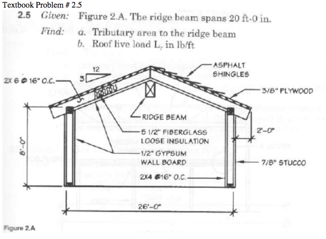
Roof live load tributary area.
So a 100 sqft deck would be designed to support 5000 lbs.
Don t get confused with what weight you might think or want to load the deck with.
Some building codes will permit the live load to be reduced only for some design members.
Minimum design loads for buildings and other structures location uniform load psf.
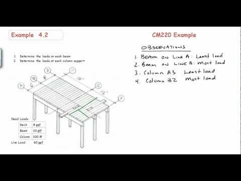
If the load is 100 psf the load to the beam would be 12 ft x 100 psf 1200 plf.
The load w that that unit length supports equals the tributary area 1 tw times the uniform pressure load q.
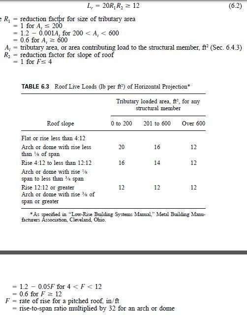
R 1 is formulated in such a way that there is no reduction for tributary areas less than 200 sqft and is maximum when the tributary area reaches 600 sqft varying linearly in between.
1 2d 1 0e l 0 2s when h loads are present they shall have 6.
Such a grid of beams reduces the span of the slab and thus permits the designer to reduce the slab thickness.
The reduction formula has two reduction terms.
Our sample homes are in an area where the snow load is 50 pounds per square foot of roof area treat snow as live load.
Example problem of determining distributed load on a beam and column reactions for a simple beam and plank system with unsymmetrical bay sizes reference.
Hence the load per that unit length is w 1 tw q q tw.
Note to builder customer.
One for the tributary area supported by the structural element r 1 and the other for the slope of the roof surface r 2.
The left wall has 7 ft of tributary width and would receive a load of 700 plf.
Tributary width is 7 ft 5 ft 12 ft.
The distribution of floor loads on floor beams is based on the geometric configuration of the beams forming the grid.
Minimum uniformly distributed live loads adapted from sei asce 7 10.
0 9d 1 0w a load factor of 1 6 when adding to load 7.
Additional collateral gravity cg and collateral uplift cu loads can be added to the building or shape as required on the live load tab as well to account for additional loading on the roof surfaces.
0 9d 1 0e effect or 0 9 when resisting the load when permanent.
The idealized beam loading diagram is shown in figure ta 2 3.
The amount of reduction allowed depends on the tributary area that a member supports and is automatically determined.
The area that it supports equals the tributary width times the unit length.